Aug 28, 2025

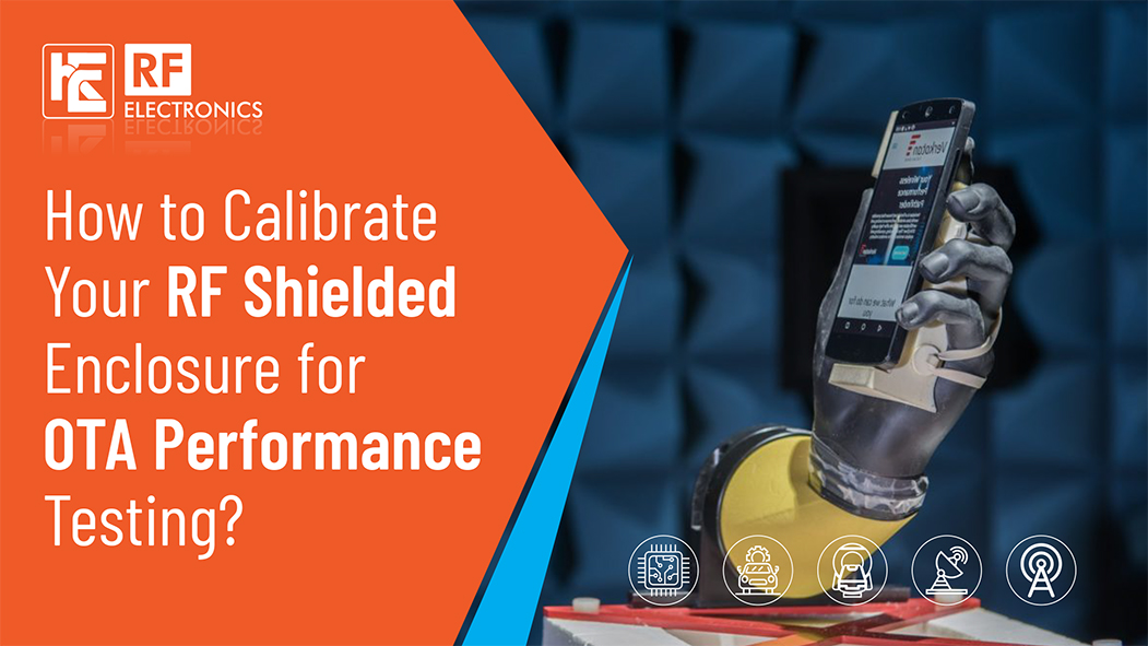
Over-the-air (OTA) performance testing in an RF shielded enclosure ensures reliable device measurements by isolating your equipment from ambient interference. Proper calibration is key. This guide walks you through a clear, actionable process to set up and align your enclosure for consistent, accurate OTA results.
A shielded enclosure or anechoic chamber blocks external RF signals and internal reflections. That quiet, controlled environment—sometimes called the “quiet zone”—lets you see a device under test (DUT) without outside noise or echoes bouncing off walls. Eliminating reflections improves both accuracy and reproducibility.
RF Electronics offers a range of shielded enclosures—from desktop boxes to full-size chambers. Select the right size based on your DUT and test goals. For a simple OTA link, you might use:
These components work together: the DUT radiates inside the box, antennas capture its signal, and analyzers or power meters log its performance.
Place a reference antenna (with known gain and pattern) inside the box. Next, install your DUT with its antenna. These need careful alignment to match polarizations and distances. Maintain consistency in placement across tests to support accurate path loss calibration.
Path loss quantifies signal strength drop between transmit and receive antennas. To calibrate:
1. Use a signal generator or golden AP with known power to transmit into the reference antenna.
2. Measure received power using the analyzer.
3. Calculate path loss (in java): Path Loss (dB) = Transmit Power (dBm) – Received Power (dBm) – GainRef – GainDUT
4. Repeat for different frequencies or angles relevant to your test.
This becomes your baseline for compensating future measurements.
OTA performance varies with frequency and antenna orientation. Scan frequencies across your DUT’s operating band, logging path loss at each. Also, rotate the DUT or reference antenna within the enclosure if your setup supports it, mapping variation across directions.
Calibration data should cover:
Use a turntable if available, or reposition manually, keeping records for reproducible results.
Once path-loss data is logged:
Example: If you measure –50 dBm from DUT at a given frequency, and your calibration indicates –10 dB path loss, infer actual radiated power as –40 dBm.
This step ensures device performance is isolated from enclosure-specific attenuation.
Calibration can drift due to temperature, hardware aging, or repositioning. Validate regularly by:
Frequent checks—weekly or monthly—help maintain test accuracy over time.
With calibration in place, measure:
RF Electronics notes these devices rely on KPIs tested in controlled, interference-free boxes. Be sure to log test conditions alongside readings for trend analysis and repeatable comparisons.
High-quality shielded enclosures use metal walls bolted or welded with RF-absorbing liners. These setups deliver consistent isolation and minimize reflections. If you notice fluctuating measurements, inspect:
Any physical issue can skew calibration data, so address them before retesting.
This audit trail makes your OTA test results defensible, especially for compliance or certification efforts.
Step Details
1. Box Inspection: Absorbers intact, RF seal intact
2. Antenna Placement: Reference and DUT antenna fixed, aligned
3. Path Loss Scan: All bands and orientations covered
4. Calibration: Correct calibration data entered
5. Validation: Checked for consistency with latest data
6. Run OTA Tests: Record KPIs under calibrated environment
7. Documentation: All steps and results logged clearly
Setting up and calibrating your RF shielded enclosure isn’t complicated—but it needs structure:
1. Provide a silent RF environment.
2. Measure baseline path loss in all relevant conditions.
3. Apply correction to DUT readings.
4. Track KPIs consistently.
5. Validate enclosure performance and calibration regularly.
Doing this makes your OTA tests reliable, accurate, and defensible. It aligns with the methods used by RF Electronics for Bluetooth, IoT, and other wireless systems.
Follow these steps, and your OTA performance data will reflect real device behaviour—not enclosure quirks. Happy testing!
Previous Blog

How AI is Revolutionizing Testing in RF-Shielded Enclosures?
Learn MoreNext Blog

How Custom RF Shield Boxes Are Engineered from Concept to Final Product
Learn More