
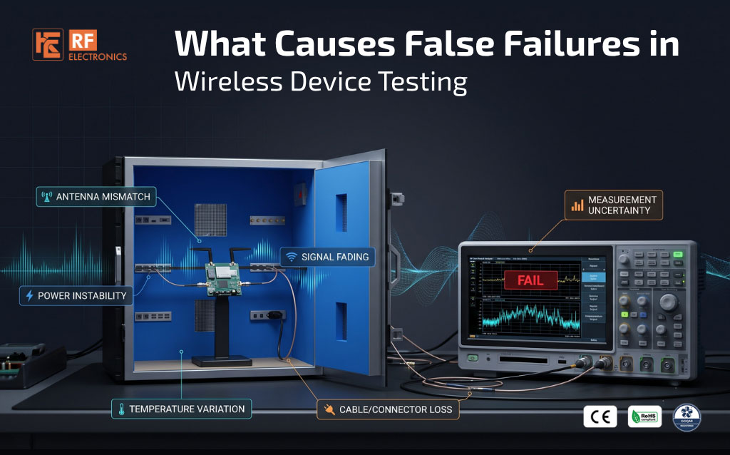
A wireless device fails a test, then passes on the next run. The changing result deserves investigation, but it does not prove that the first failure was false. The cause may be the test setup, normal measurement variation near a limit or an intermittent fault in the device itself.
A false failure occurs when the test process rejects a device that actually meets the applicable requirement. Reducing these errors starts with a repeatable setup, a defined decision rule and evidence that helps separate station problems from DUT behaviour.
Nearby Wi-Fi access points, cellular equipment, Bluetooth devices and other test stations can couple unwanted signals into a measurement. Depending on their frequency and level, these signals may affect connection stability, sensitivity, or measured emissions.
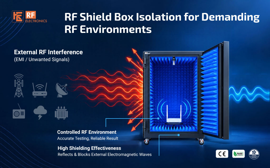
An RF shield box can reduce this coupling, but its assembled performance matters. Check door contacts, gaskets, seams, I/O plates and ventilation interfaces. Unsuitable cable entries or poorly shielded connections can create leakage paths outside the main enclosure body.
A shielding check should cover the relevant frequencies and working configuration. The presence of a box does not establish that interference has been reduced sufficiently for every test.
Stable test-path loss can be measured and compensated. Changing loss is more difficult: a damaged cable, loose connector or worn fixture contact may produce different results between runs.
Inspect cable routing, bend radius and strain relief. Use the specified connector mating procedure and torque, and avoid twisting cables during connection. Include adapters, switches and connector savers when characterising the path.
If movement changes the result, investigate the assembly rather than repeatedly adjusting a compensation value. An unstable path can affect both transmitted and received measurements.
Instrument calibration, test-path compensation and station verification serve different purposes. Instrument calibration assesses the instrument's measurement performance. Path characterisation accounts for the connected cables, adapters, fixtures and other components. Routine station verification checks whether the assembled setup continues to behave as expected.
Use the correct correction data for the frequency, path and hardware configuration. Replacing a cable or changing a switch route may require updated characterisation. A current instrument calibration certificate alone does not verify the entire station.
In over-the-air testing, the DUT position and antenna orientation affect coupling to the test antenna. Fixture tolerances, cable placement and nearby objects can alter the result even inside a shielded enclosure.
Use a repeatable fixture and document the intended arrangement. Absorber can help control reflections, but its suitability and placement must match the test. It does not eliminate every standing-wave effect or compensate for inconsistent positioning.
Check voltage at the DUT under load, not just the power supply display. Lead resistance, transient demand and supply noise can affect operation. Battery state, warm-up, temperature and thermal throttling may also change RF behaviour.
Some changes reveal a genuine DUT limitation. If a device fails under conditions required by its specification, the result should not be dismissed as a false failure simply because it passes under more favourable conditions.
Incorrect frequency, power level, bandwidth, detector, averaging or trigger settings can produce misleading results. Communication timeouts, stale readings and incorrect path selection can also cause automated tests to report failures unrelated to the intended measurement.
Record the test-script version, DUT firmware, correction-file version and relevant instrument settings. Define settling times and confirm that the test system reads a completed, valid measurement before applying the pass/fail limit.
Every measurement has uncertainty. A device close to a limit can alternate between pass and fail even when the setup is operating normally. That behaviour does not, by itself, establish which classification is correct.
Apply a documented decision rule that accounts for the measurement requirement and uncertainty. Where guardbands are used, recognise the trade-off between false acceptance and false rejection. Do not change limits or repeat tests until a passing result appears.
1. Preserve the original readings, settings, logs and DUT operating state before changing the setup.
2. Repeat according to the approved retest policy and record all outcomes.
3. Inspect connections, fixtures, power delivery and enclosure condition.
4. Verify the active test path, correction data and instrument settings.
5. Run a characterised reference device and compare its readings with its normal range.
6. Where practical, check the suspect DUT on another verified station and investigate one variable at a time.
7. If station checks are satisfactory, investigate intermittent DUT behaviour, including firmware state, temperature and mechanical connections.
8. Document the cause, corrective action and verification before returning the station to normal use.
Does passing on retest prove the first result was false?
No. It can indicate a setup issue, measurement variation or an intermittent device fault. Retain both results and investigate the cause.
Does a reference device identify the problem conclusively?
It provides useful evidence, but is not conclusive by itself. The reference device must also be stable, and one reference may not reveal every station issue.
How often should RF cables be replaced?
Use inspection results, performance checks, handling history and manufacturer guidance. Replace damaged or unstable assemblies; there is no universal interval for every cable and application.
Can a shield box eliminate false failures?
It can reduce external RF interference, but other causes remain, including path errors, software, power conditions and DUT faults.
RF Electronics can help discuss shielding, RF interconnections and fixture requirements for your wireless test environment. Combined with appropriate calibration, station verification and test procedures, these elements help reduce avoidable variation and support more reliable decisions.
Next Blog
RF Shield Box Isolation for Demanding RF Environments
Learn More

 Free Consultation


