
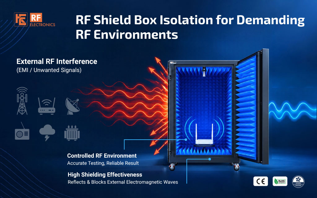
Your test environment should remain controlled even when the surrounding RF environment is not. Overhead Wi-Fi access points, neighbouring transmitters and densely populated test racks can expose a wireless test setup to unwanted RF signals. When measurements approach a receiver's sensitivity limit, even weak residual interference can influence the result.
A shield box should therefore be selected for the most demanding conditions the test setup is expected to encounter. High, verified isolation across the required frequency range provides valuable margin for sensitive measurements, changing laboratory conditions and future test requirements.
A laboratory that appears controlled can still be electrically busy. Building Wi-Fi infrastructure may operate directly above a rack. Other DUTs may transmit nearby, while multiple test stations run simultaneously. The interference environment can change with equipment placement, channel allocation and network activity.
A shield box that supports a strong-signal functional check may not provide enough isolation for testing the same device near its weakest usable receive level. Selecting against only today's favourable conditions can leave little allowance for tomorrow's test workload.
For this reason, a useful design question is: will the enclosure provide sufficient isolation when the laboratory is busy and the DUT is operating at its most sensitive test point?
Receiver sensitivity describes the lowest wanted-signal level at which a receiver meets a specified performance criterion under defined conditions. Depending on the radio, that criterion may involve packet or bit error rate and a particular bandwidth, modulation or operating mode.
Devices designed to receive very weak signals place demanding requirements on the test environment. A receiver tested around -105 dBm can be affected by interference that would be insignificant during a strong-signal check. Long-range and low-data-rate modes may therefore need particular attention when specifying the enclosure.
The relevant requirement is the most sensitive operating mode that will actually be tested. Technology names such as Wi-Fi, Bluetooth or cellular do not, by themselves, define the necessary shielding performance.
Isolation is measured in dB, while receiver sensitivity is an absolute power level measured in dBm. The two are related through an interference budget:
Residual interference in dBm ˜ unshielded interference in dBm - effective isolation in dB
The objective is to reduce unwanted signals below an allowable residual level, with suitable engineering margin. That allowable level depends on the receiver, the interfering signal and the permitted effect on the measurement.
Consider a demanding design scenario: the DUT is tested at -105 dBm, and the selected residual-interference target is 10 dB lower, at -115 dBm. If the assumed unshielded interference at the equivalent receive reference is 0 dBm, the calculated isolation requirement is 115 dB.
At exactly 115 dB attenuation, the residual reaches the -115 dBm target. Selecting verified performance above that calculated value can provide additional allowance for uncertainty and installation variation. The required allowance should be defined for the application.
The 0 dBm interference level and 10 dB separation are explicit assumptions for this example, not universal rules. If interference is stronger, more attenuation is needed. The chosen residual target must also be checked against the receiver's interference tolerance and the measurement accuracy required.
A ceiling-mounted access point near the upper part of a tall test rack is a practical example of why installation conditions matter. Short separation and antenna orientation can increase unwanted coupling into the test area.
An AP's stated transmit power is not the same as the signal level received at the DUT. Distance, frequency, antenna patterns, obstructions and reflections affect that level. Measure it at a relevant reference or use a justified design assumption that includes the anticipated operating conditions.
The purpose of a conservative interference budget is to prepare for credible demanding conditions, including nearby transmitters and simultaneous station activity. It gives the shielding requirement an engineering basis and helps avoid selecting an enclosure with insufficient margin.
A high headline isolation figure is useful only when it represents the frequencies and configuration used in the test. Performance at one frequency does not establish the same attenuation throughout the operating band.
Ask for the specified frequency range, minimum or typical attenuation, test configuration and measurement method. For a sensitivity-focused setup, identify the weakest measured performance within the relevant coverage rather than relying only on a best-case value.
The verification system must also have enough usable measurement range to support the claim. When leakage falls below its validated detection threshold, the result establishes a lower bound on isolation under the stated conditions, rather than an exact attenuation value.
Door contacts, gaskets, joints, connector interfaces and ventilation arrangements all contribute to assembled performance. High attenuation through the enclosure walls cannot compensate for an uncontrolled leakage path at an opening.
Evaluate the box with the intended I/O plate, cables, filters and cooling arrangement installed. RF ports intentionally carry wanted signals through the boundary and must form part of a controlled test path. Power and data connections need suitable treatment to preserve the intended isolation.
Repeatable door closure and maintenance are equally important. Follow the recommended cleaning and inspection procedures, and verify performance after relevant repairs, damage or interface changes.
A useful shield box should support both the current test plan and foreseeable changes. These may include more sensitive receive modes, additional test stations, different DUTs or a busier RF environment.
Specify sufficient verified isolation margin alongside frequency coverage, fixture requirements, thermal management and interface flexibility. For over-the-air testing, also consider DUT positioning, antenna coupling and internal reflections. Shielding controls external coupling; the internal test arrangement must still suit the measurement.
This approach makes high isolation a practical investment in measurement confidence. It reduces dependence on favourable surroundings and helps preserve a controlled test environment as the laboratory evolves.
No. A 115 dB requirement follows when the assumed unshielded interference is 0 dBm and the selected residual target is -115 dBm. Other interference levels or measurement tolerances lead to different requirements.
The RF environment can change. Nearby APs, additional test stations and transmitting DUTs can increase interference. Verified isolation margin helps accommodate these anticipated conditions.
No. It is an illustrative separation in the example. The acceptable residual interference depends on waveform, bandwidth, receiver response and permitted measurement error. Validate the chosen target for the actual test.
It is an important requirement, but it must be supported across the relevant frequencies and installed configuration. Interfaces, maintenance, measurement evidence and the internal test arrangement also matter.
RF Electronics helps customers define shielding requirements around demanding laboratory environments and sensitive wireless measurements. Share your frequency bands, DUT sensitivity, nearby RF sources and required interfaces so that the enclosure can be specified for its intended operating conditions.
Choose a shield box engineered for demanding RF environments, with verified isolation and sufficient margin for the measurements that matter most.
Next Blog
_(1).jpg)
Conformable vs Flexible RF Cables for Reliable RF Testing
Learn More

 Free Consultation


