
_(1).jpg)
Reliable RF measurements depend on the complete signal path. Even a high-performance instrument and a well-shielded enclosure can produce inconsistent results when a cable connection introduces changing loss, poor matching or unwanted coupling. Cable selection should therefore follow the measurement requirements as closely as the choice of instrument or shield box.
Conformable cables suit fixed routes that need to retain their shape. Flexible cables suit connections that require repositioning or motion. The best choice combines the right mechanical construction with verified electrical performance across the working frequency range.
A conformable cable can be formed by hand and generally retains its routed shape. A common construction uses tin-soaked copper braid around the dielectric, providing a formable outer conductor. Construction and the presence of a protective jacket vary by product.
The dielectric separates the centre conductor from the outer conductor; it is distinct from any external protective jacket. Conformable cable also differs from conventional semi-rigid cable, which uses a solid tubular outer conductor.
Conformable assemblies are useful for interconnections inside shield boxes, racks and fixtures where the route remains fixed. Form the cable within the manufacturer's bend limits, support it where necessary and avoid transferring bending loads to connectors. Hand-formable does not mean suitable for continuous movement.
Flexible RF cables use constructions that allow easier repositioning, often incorporating braided and foil or wrapped shielding layers. Their electrical and mechanical capabilities vary considerably.
A general-purpose flexible cable and a precision microwave test cable can perform very differently. For repeated motion, select an assembly with appropriate flex-life, bend-radius and torsion specifications. Flexibility alone does not guarantee that a cable will survive automated cycling or maintain its electrical characteristics during movement.
|
Selection factor |
Conformable |
Flexible |
|
Typical installation |
Fixed routed interconnections |
Repositioned or moving connections |
|
Shape retention |
Generally retains formed route |
Usually needs routing support |
|
Repeated motion |
Not generally intended for continuous flexing |
Requires a suitable movement rating |
|
Loss and matching |
Check assembly specifications |
Check assembly specifications |
|
Phase stability |
Check installation and temperature effects |
Check movement and temperature effects |
|
Bend limits |
Follow forming instructions |
Check static and dynamic limits |
Insertion loss should be compared at the same frequency and assembly length. Include connector and adapter losses in the complete test path. Cable diameter, dielectric, conductor construction and frequency all affect the result; the category name alone does not establish which assembly has lower loss.
Return loss describes impedance matching: a higher return-loss value indicates a smaller reflected signal under the stated conditions. Check matching across the working band and, for moving applications, assess whether handling changes it. Good performance in a straight, stationary condition may not represent the installed route.
Phase and amplitude stability matter when small changes can affect a measurement. Ask for specifications versus bending and temperature where relevant. A stationary conformable assembly can provide a stable interconnection, while a purpose-designed flexible test cable can offer excellent stability during normal handling.
Shielding performance deserves particular attention in sensitive receiver tests and dense production setups. Unwanted coupling through the cable assembly or its connectors can affect the result. Evaluate shielding over the relevant frequencies, including connector transitions and installed routing. Cable shielding and enclosure isolation are different specifications; their dB values should not simply be added to claim overall system isolation.
Consider a path whose measured insertion loss is 2.0 dB at the test frequency. If handling changes that loss to 2.5 dB while the system still applies the original correction, a 0.5 dB path error remains. That difference can matter when a result is close to a pass or fail limit.
This illustrates why low insertion loss and stable insertion loss are both important. The example does not describe the expected behaviour of either cable category. Check the actual assembly under representative routing, temperature and movement conditions.
For fixed connections inside an RF shield box or equipment rack, a conformable assembly can simplify routing and keep cables clear of fixtures and moving parts. Allow enough access for assembly and service without forcing the connectors into alignment.
For VNA measurements involving frequent DUT changes, consider flexible test-port cables with specified phase and amplitude stability. Complete the measurement calibration with the cables in their intended configuration, then minimise movement. Fixed conformable interconnections may suit dedicated fixtures, provided the calibration and reference plane account for them.
For antenna positioners and moving fixtures, choose flexible assemblies rated for the actual motion. Check dynamic bend radius, strain relief and twist limits. A cable suitable for occasional bench repositioning may not suit continuous automated use.
Nearby access points and adjacent transmitting DUTs can create unwanted RF coupling around a test station. High enclosure isolation is only one part of controlling that environment. RF cables, bulkhead connectors and other interfaces must also suit the measurement.
An RF port intentionally passes the wanted signal through the enclosure boundary. A shielded cable does not block interference already carried along that intended signal path, and it does not make an unsuitable enclosure penetration acceptable. Assess routing, port connections and any application-specific filtering as part of the complete setup.
For low-level receiver testing, verify the assembled path with representative equipment activity nearby. Avoid relying on a cable category or jacket appearance as evidence of shielding performance.
Route cables before calibrating or characterising the test path. Respect bend limits, use the specified connector mating procedure and torque, and avoid twisting the assembly while tightening it. Connector savers may be useful where frequent mating is expected, but they must be included in the path assessment.
Record a baseline and investigate unexpected changes in insertion loss, matching or repeatability. Replace damaged assemblies rather than attempting to compensate for an unstable connection through software.
Provide the operating frequency range, characteristic impedance, assembly length and exact connector interfaces, including gender and orientation. State insertion-loss and matching requirements, power level, temperature range and any phase or amplitude stability limits.
Describe whether the cable will remain fixed, be repositioned occasionally or flex continuously. Include the available bend radius, routing constraints and connector mating frequency. For automated movement, define the motion and expected duty rather than assuming that any flexible cable is suitable.
Where measurement performance is critical, request relevant assembly-level test data and agree how acceptance will be checked. Connector mating life, cable flex life and electrical stability are separate considerations.
Can conformable cable be reshaped
Limited reforming may be possible within the manufacturer's instructions. It should not be treated as a cable for repeated dynamic bending.
Which cable offers better phase stability
Compare the specified phase change under the expected temperature and movement conditions. Neither cable category guarantees better phase stability in every application.
Does a high isolation shield box remove the need for good cable shielding
No. Cables and interfaces can provide additional unwanted coupling paths. Verify the enclosure and the connected RF path in their intended configuration.
Can flexible cables be used at microwave frequencies
Yes, if the complete assembly and connectors are rated for the required frequency and meet the measurement requirements.
What should I specify when requesting a cable assembly
Provide the frequency range, impedance, length, connectors, acceptable loss and matching, power level, routing constraints and expected movement. Include phase-stability and environmental requirements when relevant.
Share your frequency range, connector configuration, routing and measurement requirements with RF Electronics. Whether the connection is fixed inside a shield box, regularly handled on a bench or integrated into a moving fixture, selection should focus on the complete assembly and its intended use. A well-specified RF interconnection supports repeatable measurements and reduces avoidable setup-related troubleshooting.
Previous Blog
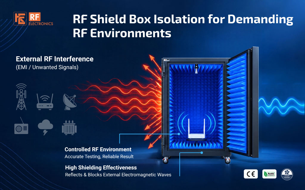
RF Shield Box Isolation for Demanding RF Environments
Learn MoreNext Blog
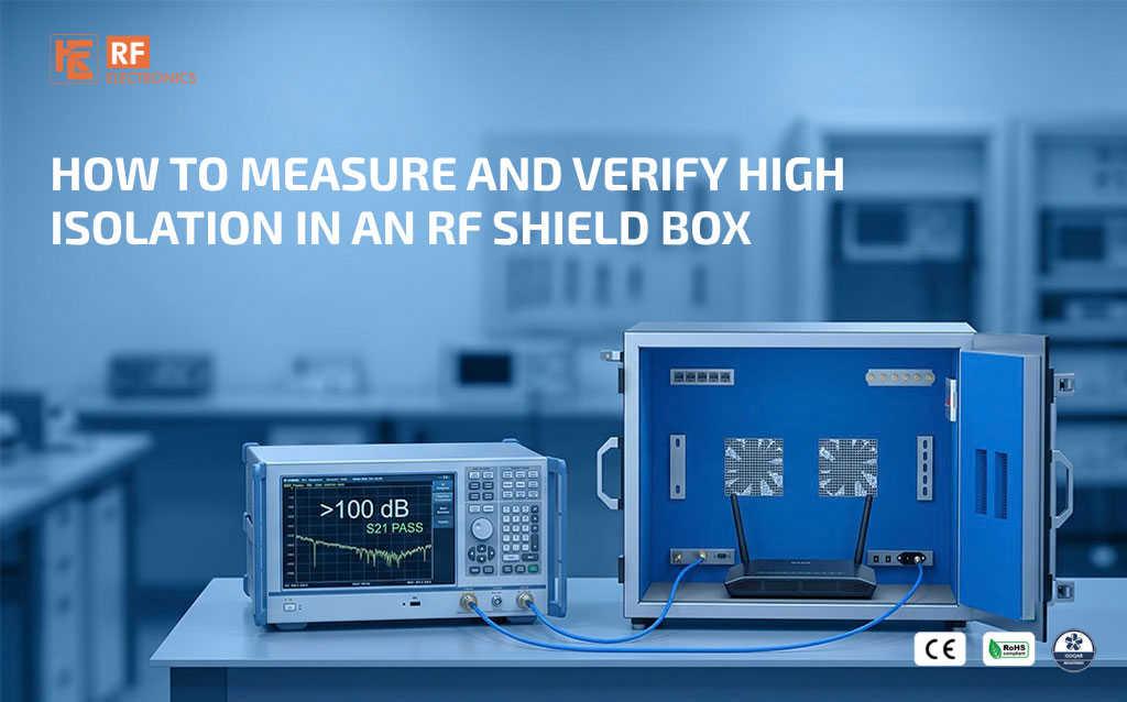
How to Measure and Verify High Isolation in an RF Shield Box
Learn More

 Free Consultation


