
Oct 05, 2026
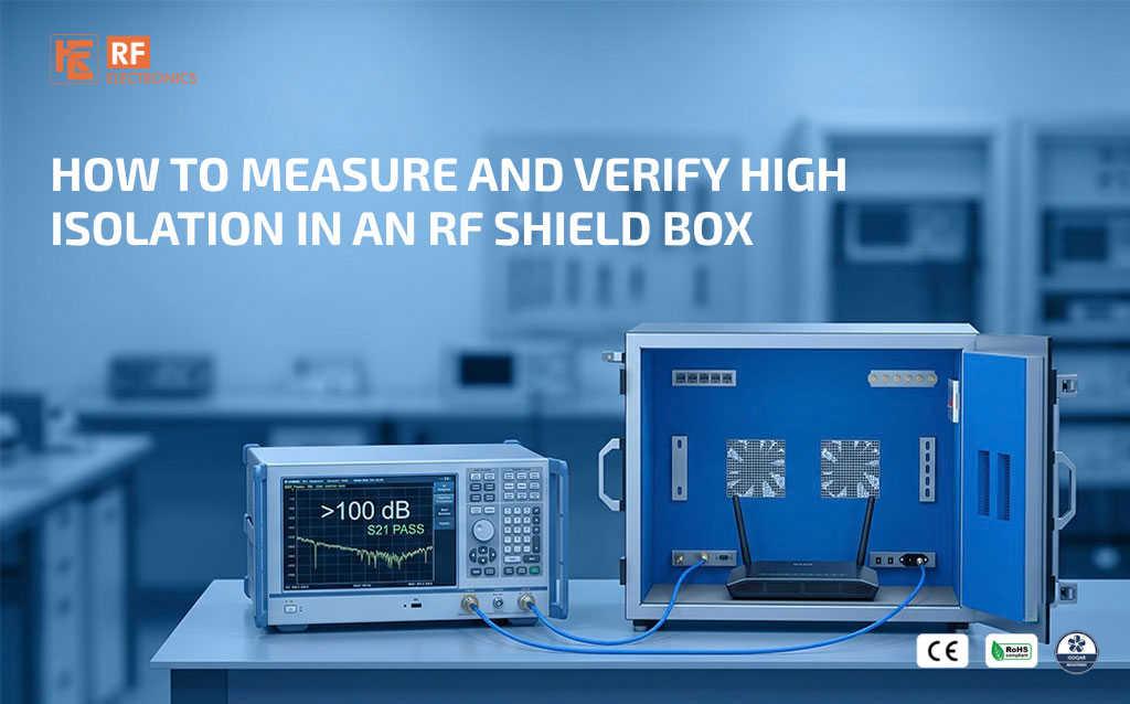
A shield box intended for demanding RF environments needs more than a high isolation figure on a datasheet. Its performance must be verified across the required frequencies, with the interfaces and operating configuration used in the actual test setup. This becomes especially important when testing receivers near their weakest usable signal levels.
Nearby Wi-Fi access points, adjacent transmitters, and active test racks can make the surrounding RF environment unpredictable. A well-defined shielding measurement establishes how much the enclosure attenuates unwanted coupling and whether the result supports the intended isolation requirement.
The required shielding comes from the test conditions. As an illustrative design case, a receiver tested at -105 dBm may use a residual-interference target of -115 dBm. With an assumed unshielded interference level of 0 dBm at the equivalent receive reference, the calculated requirement is 115 dB isolation. The interference level and 10 dB separation are assumptions to validate for the application, not universal requirements.
Once the target is defined, the verification method must be capable of demonstrating it. The receiver sensitivity used to select the enclosure is different from the measurement receiver’s detection capability used to verify the enclosure.
Shielding effectiveness is expressed in decibels. For a received-power comparison under equivalent measurement conditions, it can be calculated as:
SE in dB = reference received power in dBm - shielded received power in dBm
For example, a received reference level of -10 dBm and a reliably measured shielded level of -125 dBm indicate 115 dB attenuation at that frequency and configuration. Both values must be referred to equivalent measurement conditions. Any changes in source power, receiver gain or measurement-path loss must be accounted for.
This is not simply a comparison between generator output power and the received leakage signal. That difference also includes antenna coupling and other path losses.
Specify the frequency range, required attenuation, reference arrangement, antenna positions, polarisations and enclosure configuration. State whether the work is a routine comparative check, an engineering characterisation or a test against a specified procedure.
An open-lid measurement, an enclosure-absent measurement and a cable bypass are different reference arrangements. Opening a lid changes reflections and antenna coupling. A direct cable bypass removes the radiated path. Do not treat these arrangements as interchangeable.
An open-lid comparison can support routine checks when validated for the particular setup. Formal performance claims require a suitable documented method with its geometry and limitations understood.
A typical arrangement uses a stable RF signal generator, suitable transmitting and receiving antennas, and a spectrum analyser or measurement receiver. A network analyser can also be used where its dynamic range and leakage performance suit the method.
Place transmitting and receiving antennas on opposite sides of the shielding boundary. Use suitable cable assemblies and correctly engineered feedthroughs. The measurement wiring must not create an uncontrolled leakage path or bypass the enclosure.
Choose antennas appropriate to the frequency range and available space. Calibration information is useful, but it does not remove errors caused by uncontrolled placement, mismatch or coupling. Keep measurement geometry repeatable and document the installed accessories.
If the RF source is placed inside the enclosure, its power and control arrangements must preserve the shielding boundary. Suitable options may include battery operation, properly filtered power and fibre-based control through a correctly designed optical entry. Do not route an unfiltered conductive cable through a door gap or an entry intended only for optical fibre. Document the arrangement used.
Before claiming a high attenuation value, verify that the system can resolve it. Measure the background with the source off, check instrument noise and unwanted coupling, and confirm that the stronger reference signal does not overload the receiver.
With a received reference of -10 dBm, 120 dB attenuation corresponds to a shielded level of -130 dBm. An exact measurement therefore requires the setup to resolve that level with adequate separation from noise and other unwanted responses. A nominal receiver noise-floor figure alone does not establish this capability.
Record receiver bandwidth, detector, averaging, attenuation and preamplifier settings. Keep settings consistent where possible and account for verified differences where changes are necessary. A peak near the noise floor should not automatically be identified as leakage from the test source.
Suppose the received reference is -10 dBm and the validated detection threshold is -120 dBm. The nominal available range is 110 dB. If the test signal is undetectable with the box closed, the result supports a measurement-limited bound of approximately 110 dB, subject to uncertainty and the reporting rule. It does not establish 115 dB or 120 dB performance.
To extend the usable range, the method may employ higher source power, lower receiver bandwidth or suitable low-noise amplification. Each change must be validated: higher source levels can overload equipment, narrower bandwidth requires appropriate settling, and amplification can introduce compression or unwanted coupling. Establish a usable range at every relevant frequency.
Check the response at the intended test frequency with the source on and off. Where practical, vary the source level by a known amount and verify a corresponding response while remaining within the linear range. This helps distinguish source-related leakage from background signals or instrument noise.
Source-related response alone does not prove that the signal crossed the shielding boundary. Leakage from instruments, external cables or control wiring can bypass the enclosure and limit the test. Investigate these paths separately before attributing the response to the box.
1. Inspect the door contacts, gaskets, seams, connectors and ventilation interfaces. Assemble the enclosure in the configuration being evaluated.
2. Verify instrument operation and establish the reference response according to the selected method.
3. Check background signals, system leakage and usable measurement range across the test band.
4. Close and latch the enclosure normally. Measure the shielded response without introducing unintended changes to the test paths.
5. Repeat across the required frequencies, antenna polarisations and defined positions. Include locations relevant to doors, seams, vents and I/O interfaces.
6. Repeat selected measurements and door closures to assess repeatability. Recheck the reference if drift is suspected.
7. Report attenuation versus frequency, measurement-limited results, tested configurations and relevant uncertainty.
A strong result at one frequency does not establish performance across an entire band. Resonances, apertures, seals and interfaces can produce frequency-dependent variations. Use enough frequency resolution to investigate unexpected dips, and identify the lowest measured attenuation within the defined test coverage.
Absorber can reduce internal reflections, but it does not replace a conductive enclosure and effective seams. Test with the intended absorber, I/O plates and ventilation arrangement, because a change in configuration may affect the measured response.
Compare the results with the isolation budget for the most sensitive operating mode being tested and the anticipated external interference. Use a defined acceptance rule that accounts for measurement uncertainty. Where the available measurement range cannot establish compliance, report the result as inconclusive against that requirement rather than treating non-detection as an automatic pass.
Record the enclosure model and serial number, date, installed I/O and ventilation configuration, test method, instruments and calibration status. Include antenna positions and polarisations, source levels, receiver settings, reference and shielded readings, and the validated measurement limit across the test band.
Present attenuation versus frequency and identify the lowest result within the tested positions and polarisations. Mark measurement-limited results explicitly, state relevant uncertainty and the acceptance rule, and record any deviations from the planned method. This makes the result traceable and supports later maintenance comparisons.
Is opening and closing the lid enough to measure shielding?
It can provide a comparative check if the setup is validated and repeatable. It should not automatically be treated as a formal measurement of enclosure shielding effectiveness.
Can an undetectable signal be reported as zero leakage?
No. State the measurement limit and report the corresponding lower bound on attenuation under the documented conditions.
How often should a shield box be checked?
Set the interval according to usage, maintenance history and test criticality. Verify performance after relevant repairs, damage or changes to seals and interfaces.
Does enclosure size affect the measurement?
Yes. Size relative to wavelength affects resonances, antenna placement and coupling, alongside the performance of seams and interfaces.
RF Electronics can help define shield-box selection and verification requirements around sensitive wireless measurements and demanding RF environments. Share the frequency bands, DUT sensitivity, anticipated interference, target isolation and required interfaces so that performance can be evaluated under relevant conditions.
Next Blog
RF Shield Box Buying Guide Everything Engineers Need to Know
Learn More

 Free Consultation


